Basic principles of acousto-optic theory, on which acousto-optic devices are based on

AA Opto-Electronic
18, rue Nicolas Appert 91898 Orsay France
Tél.: 33 (0)8 11 09 76 76 - 33 (0)1 76 91 50 12 - Fax: 33 1 76 91 50 31
email: sales@a-a.fr - www.aaoptoelectronic.com
Acouto-Optics
Radio Frequency
Laser applications

ACOUSTO-OPTIC PHYSICAL PRINCIPLES - MAIN EQUATIONS

An RF signal applied to a piezo-electric transducer, bonded to a suitable crystal, will generate an acoustic wave. This acts like a “phase grating”, traveling through the crystal at the acoustic velocity of the material and with an acoustic wavelength dependent on the frequency of the RF signal. Any incident laser beam will be diffracted by this grating, generally giving a number of diffracted beams.


Interaction conditions

A parameter called the “quality factor, Q”, determines the interaction regime. Q is given by:
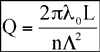

where is the wavelength of the laser beam, n is the refractive index of the crystal, L is the distance the laser beam travels through the acoustic wave and is the acoustic wavelength.

Q<<1 :This is the Raman-Nath regime. The laser beam is incident roughly normal to the acoustic beam and there are several diffraction orders (...-2 -1 0 1 2 3...) with intensities given by Bessel functions.

Q>>1 : This is the Bragg regime. At one particular incidence angle , only one diffraction order is produced - the others are annihilated by destructive interference.

In the intermediate situation, an analytical treatment isn't possible and a numerical analysis would need to be performed by computer.

Most acousto-optic devices operate in the Bragg regime, the common exception being acousto-optic mode lockers and Q-switches.


Wave vectors constructions

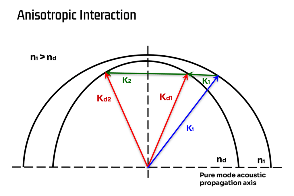
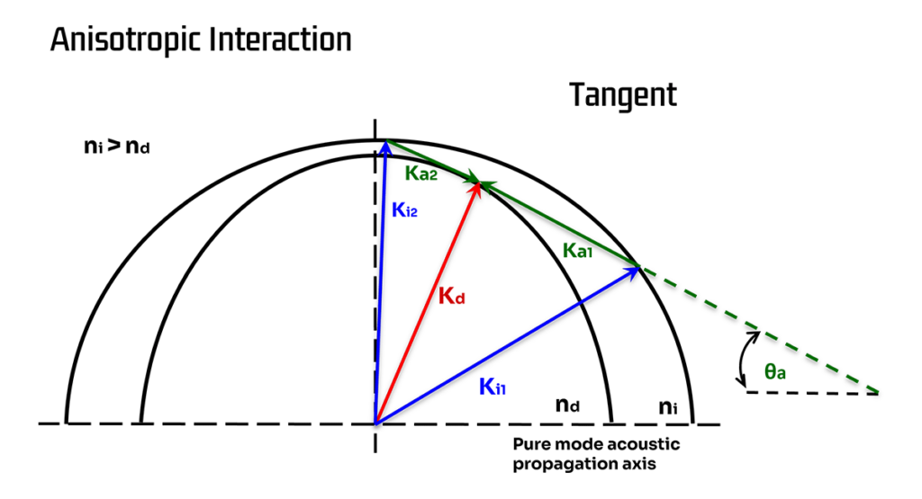
An acousto-optic interaction can be described using wave vectors. Momentum conservation gives us

- wave vector of the incident beam.
- wave vector of the diffracted beam.
- wave vector of the acoustic wave.

Here F is the frequency of the acoustic wave traveling at velocity v. ni and nd are the refractive indexes experienced by the incident and diffracted beams (these are not necessarily the same).

Energy conservation leads to : Fd = Fi +/- F

So, the optical frequency of the diffracted beam is by an amount equal to the frequency of the acoustic wave. This “Doppler shift” can generally be neglected since F<<Fd or Fi, but can be of great interest in heterodyning applications.

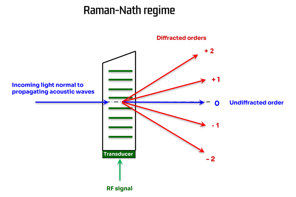
Acousto-optic components use a range of different materials in a variety of configurations. These can be heard described by terms such as longitudinal- and shear-mode, isotropic and anisotropic. While these all share the basic principles of momentum and energy conservation, these different modes of operation have very different performances - as shall be seen.


Characteristics of the diffracted light

Isotropic Interactions

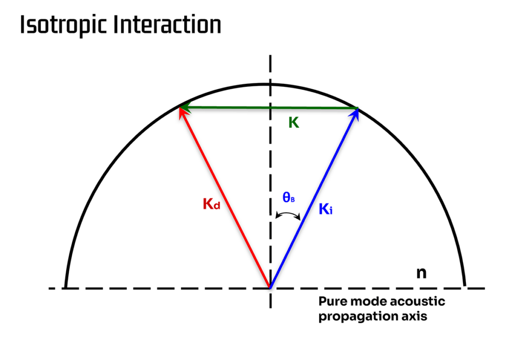
An isotropic interaction is also referred to as a longitudinal-mode interaction. In such a situation, the acoustic wave travels longitudinally in the crystal and the incident and diffracted laser beams see the same refractive index. This is a situation of great symmetry and the angle of incidence is found to match the angle of diffraction. There is no change in polarization associated with the interaction.
These interactions usually occur in homogenous crystals, or in birefringent crystals cut appropriately.

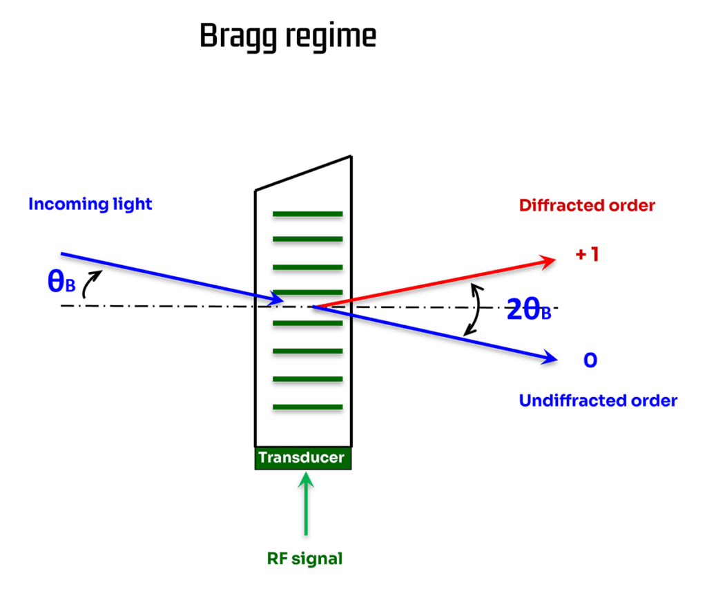
In the isotropic situation, the angle of incidence of the light must be equal to the Bragg angle, :

where is the wavelength inside the crystal, v is the acoustic velocity and F is the RF frequency.

The separation angle between the first order and zero order beams is twice the angle of incidence and, therefore, twice the Bragg angle.

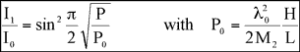
The diffracted light intensity I1 is directly controlled by the acoustic power P

Here I0 is the incident light intensity, M2 is the acousto-optic figure of merit for the crystal and H and L are the height and length of the acoustic beam. is the wavelength of the incident beam.

Diffraction efficiency (relative) is the ratio I1/I0:

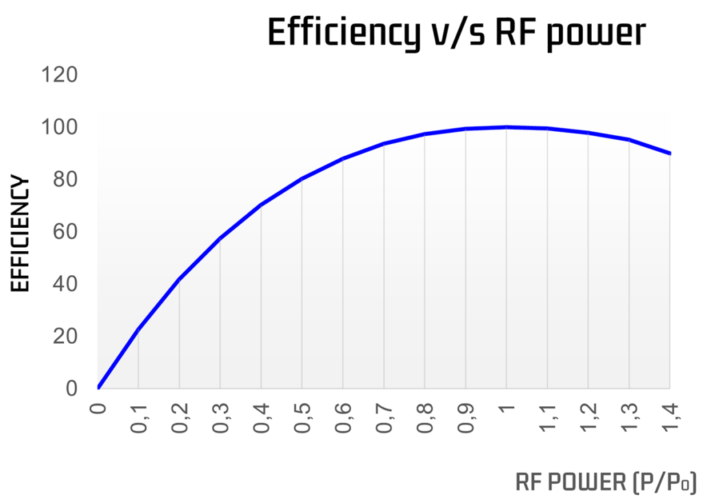
For a given orientation, if the RF frequency is slightly different from that required to match the Bragg criterion, diffraction will still occur. However, the diffraction efficiency will drop. The situation is shown in the figure below, where the acoustic wave-vector, K, is longer than the ideal “Bragg” wave-vector, K0.

A complicated analysis leads to the result:
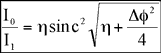
where and is called the “phase asynchronism”.

In the isotropic case :

At the correct Bragg frequency, and efficiency is maximum
When increases, diffraction efficiency decreases and will continue to decrease down to zero.
If there is a lower limit on the acceptable diffraction efficiency, then this puts a limit on . This, in turn, implies a maximum - and defines the RF bandwidth for the device.
To increase this RF bandwidth, the ratio (the acoustic divergence) can be increased.
As the RF frequency varies, the diffracted beam's direction changes. This is the basis behind acousto-optic deflectors.


Anisotropic interaction

In an anisotropic interaction, on the other hand, the refractive indexes of the incident and diffracted beams will be different due to a change in polarization associated with the interaction. This can be seen in the figure below where the acoustic wave vector K1 connects the index curves of the incident and diffracted waves. (K2 simply represents a similar interaction at a very different RF frequency).

The same asymmetry which causes the difference in refractive indexes also causes the acoustic wave to travel in a “shear-mode” and, in the particular example of tellurium dioxide, this results in a drastic reduction in the acoustic velocity.

Anisotropic interactions generally offer an increase in efficiency and in both acoustic and optical bandwidth. They are used almost universally in large aperture devices. The reduction in the acoustic velocity, seen in shear-mode tellurium dioxide, lends this material to be used in high resolution deflectors.

The increased bandwidth available from shear-mode devices can be seen most immediately in the figure below where the interaction configuration is chosen so that the acoustic wave-vector lies tangential to the diffracted beam's index ellipse.


This means that the length of the acoustic wave-vector can vary quite grossly while only producing small changes in the length of the diffracted beam's wave-vector. So, in this situation, (and, hence, ) is quite insensitive to changes in RF frequency.

Shear-mode interactions are very much more complex to analyze, requiring detailed information on crystal cut, refractive indexes, orientation. However, these

interactions have a lot of advantages and most deflectors and all AOTFs will use shear-mode interactions. The reduced acoustic velocity makes these devices very much slower than longitudinal-mode units and this can be seen as a disadvantage in some circumstances.

Enter online catalogue

AA Opto-Electronic 18, rue Nicolas Appert 91898 Orsay France
Tél: +33 (0)8 11 09 76 76 - +33 (0)1 76 91 50 12 - Fax: +33 (0)1 76 91 50 31
email: sales@a-a.fr - www.aaoptoelectronic.com

Acousto-Optic History
Acousto-Optic Glossary
Acousto-Optic physical principles - Main equations
Acousto-Optic effects on the light beam
Constitution of a Bragg Cell
Acousto-Optic material
AA-Presentation